What Are Solar Panels Made Of? Structure, Types & Installation Explained
Inside a panel layer by layer, the difference between mono and poly, and the roof checks that turn panels into a working array.
This is Solar Basics, Part 2 of 5. In Part 1 we covered why sunshine matters, what photovoltaic means, the four home-system components, and the idea of cell → panel → array. Here we open the panel itself, name the common types, and walk through how panels are tilted, racked, wired, and run in conduit on a roof.
What a solar panel is made of
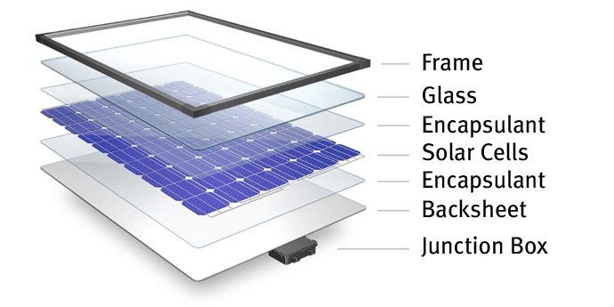
A finished solar panel (PV module) looks like one flat sheet of glass. Inside, it is a stack of layers, each with one job: let light in, hold the cells, keep water out, and take electricity out safely.
Glass
The front is almost always tempered glass — strong, weather-resistant glass that faces the sun. It has to be clear enough for sunlight to reach the cells, and tough enough for hail, wind-blown grit, and cleaning. Think of it as the windshield of the panel.
EVA (encapsulant)
EVA stands for ethylene vinyl acetate. In plain English, it is a clear plastic “glue sheet” that softens when the panel is laminated in the factory. There is usually a layer above and below the cells. Once cured, EVA bonds the glass to the cells and the cells to the backsheet, filling gaps so moisture and dirt cannot sit on the active surface. Diagrams often label this simply as encapsulant.
Solar cells
The cells are the working parts — thin wafers (usually silicon) that turn light into DC electricity. They are wired together inside the laminate so their voltages and currents add up to the panel’s rated output. Part 1’s rule of thumb still applies: one cell is roughly half a volt; a panel is many cells sealed as one product.
Backsheet
The backsheet is the rear skin of the panel — often a white or dark polymer film. It electrically insulates the cells from the outside world and protects them from water and UV from behind. Glass-glass modules exist too, but the classic teaching stack is glass + encapsulant + cells + encapsulant + backsheet.
Frame
An aluminium frame wraps the edges. It stiffens the module so it can be clamped onto mounting rails without cracking the glass, and it gives installers a standard edge to hold and bolt. Frameless modules exist for special roofs; most home rooftop panels are framed.
Junction box
On the back of the panel sits a small sealed box called the junction box. The ribbons from the cells terminate here. The box usually includes bypass diodes (so shaded cells hurt the string less) and the positive and negative cables that leave the panel. When installers “connect panels,” they are plugging those cables together — not opening the laminate.
Types of solar panels (and cells)
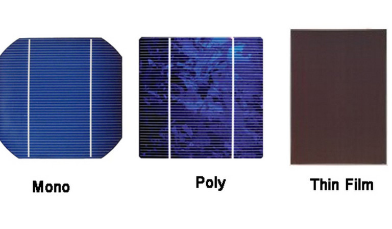
“Type” usually means how the silicon (or other material) was made. You can often spot the difference by eye.
Monocrystalline (mono)
Monocrystalline cells are cut from a single crystal of silicon. Because the crystal structure is orderly, electrons move with less internal resistance, so mono panels are typically the most efficient of the common silicon types for a given area. They often look uniformly dark, and older mono cells had clipped corners (pseudo-octagon shape) from the round crystal ingot.
Polycrystalline (poly)
Polycrystalline cells are cast from many silicon crystals melted together. You see a speckled, “shattered ice” blue look. They are square with sharp corners. Historically they were a bit less efficient per square metre than mono, but they taught the same physics and still power many roofs. For a homeowner, the practical difference is mostly efficiency and appearance — not a different kind of electricity.
Thin film
Thin-film modules deposit a very thin semiconductor layer onto glass or another substrate. They often look smooth and dark, without the busbar grid you see on crystalline cells. They can be lighter or more flexible in some product lines, but usually need more roof area for the same power. For most Indian home rooftops today, crystalline silicon (mono or poly) is what you will meet first.
Installation: checks before the first panel goes up
Good installation is not only “bolting panels on a roof.” Before and during the job, installers run a short list of mandatory checks: Is the roof structure sound for the extra weight and wind load? Is the roof free of long shade from trees, water tanks, or neighbouring buildings at peak sun hours? Are cable paths planned so water cannot follow wires into the house? Are earthing and lightning protection considered for that site? Skipping these turns a clean electrical design into a leaky or shaded disappointment.
One wiring detail that shows up again and again in field practice: use adequate conductor size for panel-to-panel links. A common teaching standard for panel interconnection cable is 4 sq.mm copper (four square millimetres cross-section) — thick enough for typical string currents with acceptable voltage drop and heating, when the rest of the design matches. Undersized interconnect wire is a quiet way to lose energy as heat and to invite failures at connectors.
Latitude and tilt angle
Latitude is how far north or south you are from the equator, measured in degrees. Chennai sits much closer to the equator than Delhi; Srinagar is farther north still. The sun’s path across the sky changes with latitude, so the “best average” panel angle changes too.
Tilt angle is how much the panel is leaned up from flat. Flat is 0°; a wall is 90°. A simple year-round rule of thumb for fixed rooftop arrays facing true south in the Northern Hemisphere is: set tilt roughly equal to the site’s latitude. Delhi near 28°N often uses a steeper tilt than a city near 13°N. Seasonal tweaks exist (steeper in winter, flatter in summer), but the latitude rule is the teaching starting point. Facing the wrong direction or lying almost flat in a high-latitude city wastes free sunshine.
Racks: what holds the panels
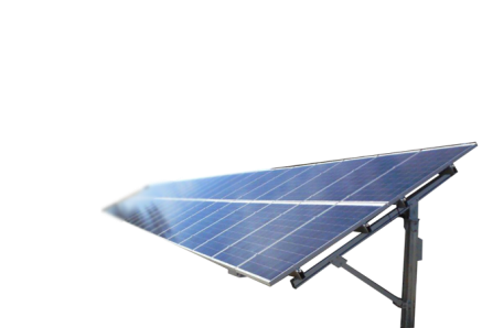
A rack (mounting structure) is the metal skeleton under the panels — rails, clamps, legs or posts, and fasteners into the roof or ground. Its jobs are mechanical: keep the chosen tilt and orientation, survive wind, shed water correctly for that roof type, and leave a small air gap under the modules so they can cool. Panels do not sit loose on tiles; they sit on engineered racks designed for that roof (flat RCC terrace, metal sheet, pitched tile, and so on).
Array formation: series and parallel
An array is simply more than one panel working together. How you wire them changes voltage and current:
- Series (positive of one to negative of the next): voltages add; current stays about the same as one panel. A “string” of panels in series is how many rooftop systems raise voltage for the inverter or charge controller.
- Parallel (positives together, negatives together): currents add; voltage stays about the same as one panel (or one string). Parallel paths are used when you need more amps at a given voltage.
Real roofs often combine both: several series strings, then those strings in parallel. The design must match what the inverter or charge controller can accept — that matching is Part 3’s territory.
Conduiting from the rooftop
Conduit is a protective tube (metal or PVC) that carries cables from the roof array down to the equipment room. It shields insulation from sun, rain, rodents, and accidental knocks, and it keeps cable runs neat and inspectable. DC cables from the panels should not hang unprotected across a terrace forever.
Path and termination differ slightly by system type. On an on-grid rooftop system, conduit often runs toward the grid-tied inverter and the utility metering / AC interconnection point in the house. On an off-grid rooftop system, the same roof cables still need conduit — but they typically head to the charge controller, battery bank, and off-grid inverter instead of a grid-export meter. The physics of protecting the cable is the same; the destination equipment is what changes.
What’s next
You can now name the layers inside a panel, tell mono from poly from thin film, and follow an install from mandatory checks and interconnection wire through tilt, racks, series/parallel arrays, and conduit — including why on-grid and off-grid roofs may route to different equipment.
Part 3 — How to Size a Solar System for Your Home (Load, Panels, Inverter & Battery) — starts from loads (Wh), then sizes modules, inverter, and battery so the numbers fit each other.
- System sizing — load, modules, inverter, battery
- On-grid vs off-grid — how each case works
- Standards and practical buying checklist
Start from the beginning: Solar Basics Part 1 — Let the Sun Pay Your Electricity Bills.
— Kunwer Sachdev
Solar Man of India